
Slip-form shuttering and pneumatic rammer compaction are the high-efficiency mechanical tools of contemporary rammed earth construction. Reusable modular forms constructed from 21mm film-faced plywood and aluminum walers withstand extreme lateral compaction forces (50–65 kN/m²), while handheld pneumatic tampers operating at 90 PSI compact loose 150mm soil lifts into ultra-dense 100mm stone-like strata.
At a Glance: Key Takeaways
- Heavy-Duty Slip-Forms: Modular formwork panels designed for rapid stripping, lifting, and re-clamping up the height of the wall.
- 50 kN/m² Lateral Pressure Rating: Reinforced with external structural steel or aluminum strongbacks to prevent form bulging under ramming.
- Reusable Through-Tie Sleeves: Tapered plastic sleeves allowing high-tensile tie-rods to be extracted cleanly without damaging the cured wall.
- High-Frequency Pneumatic Tampers: Backfill tampers (pogo sticks) running on 90 PSI compressed air delivering 600–800 blows per minute.
- Auditory Density Feedback: The tamper sound changes from a dull thud to a sharp, high-pitched metallic ringing when maximum compaction is reached.
- Chamfered Internal Edge Fillets: 45-degree triangular timber fillets placed at corners to eliminate fragile 90-degree earth edges.
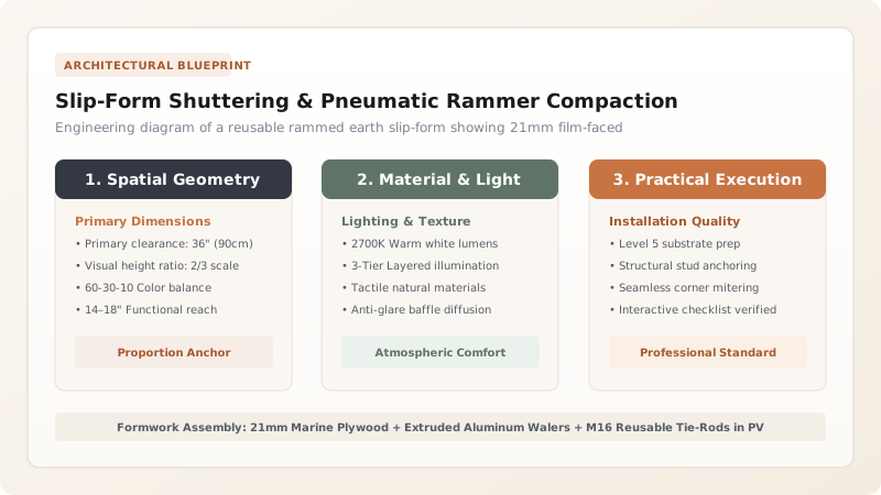
1. Shuttering Engineering: Resisting High Dynamic Compaction
Unlike concrete formwork—which resists hydrostatic fluid pressure that peaks at the bottom—rammed earth formwork experiences intense dynamic point impact loads from pneumatic rammers operating directly against the formwork face.
Lateral pressures routinely spike at \(50\text{ to }65\text{ kN/m}^2\). To prevent form bowing (which creates unsightly wavy wall faces), master builders utilize:
- 21mm Birch Phenolic Film-Faced Plywood: Smooth, non-porous face that releases cleanly from damp earth without pulling off surface crusts.
- Double Aluminum/Steel Walers (Strongbacks): Paired horizontal channels spaced every \(600\text{ mm}\) vertically to stiffen the plywood.
- M16 High-Tensile Through-Ties: Spaced every \(750\text{ mm}\) horizontally, encased in smooth rigid PVC sleeves that allow immediate extraction after ramming.
2. Compaction Mechanics: Pneumatic Tampers & Lift Density
Manual wooden rammers (pisoirs) were used historically, but contemporary construction relies on pneumatic backfill rammers (such as Ingersoll Rand or Chicago Pneumatic models) driven by a \(185\text{ CFM}\) diesel compressor at \(6.2\text{ bar}\) (\(90\text{ PSI}\)).
Soil must be placed in loose lifts of exactly \(150\text{ mm}\). Ramming compacts the layer down to \(100\text{ mm}\) (a 33% volumetric reduction):
If loose lifts exceed 180mm, the bottom of the lift will remain under-compacted, creating weak, friable strata prone to accelerated water erosion.
3. The Slip-Form Workflow & Immediate Striking
Unlike concrete—which must remain in forms for days while cement hydrates—rammed earth relies on instantaneous aggregate friction and capillary suction. Forms can be struck immediately upon reaching the top of the panel.
The form is unbolted, hoisted up using mobile cranes or wall-mounted climbing jacks, and re-clamped over the top 100mm of the compacted wall below. Workers use wire brushes to groom the exposed damp wall, lightly exposing fine aggregate for a natural stone-like texture.
Slip-Form Shuttering & Tamper Specifications
Use this reference table to calculate exact physical dimensions, ratios, and specifications before purchasing:
| Equipment / Component | Engineering Specification | Operational Tolerance | Safety / Quality Note |
|---|---|---|---|
| Formwork Facing | 21mm Russian birch film-faced plywood | Deflection < L/400 between walers | Zero plywood grain telegraphing on earth face |
| Waler Strongbacks | Double 100x50mm structural aluminum channels | Spaced 600mm on center vertically | Prevents lateral bulging under tamper blows |
| Through-Tie Rods | M16 Grade 8.8 high-tensile steel all-thread | Encased in 22mm OD rigid PVC sleeves | Tie holes patched with matching color earth paste |
| Pneumatic Tamper | 6kg handheld pneumatic backfill rammer | Operated at 90 PSI (6.2 bar) line pressure | Requires operator anti-vibration gloves & ear defense |
| Loose Lift Depth | Strictly 140 to 160 mm depth | Uniform rake leveling before tamping | Thicker lifts leave soft uncompacted bottoms |
| Compacted Lift Depth | 95 to 105 mm dense strata | Compacted until metallic ring sounds | Dry bulk density verified > 2,100 kg/m³ |
Site Operations & Mechanical Constraints
Every successful decoration project must account for physical and environmental constraints:
Formwork Alignment Drifts
Slip-forms tend to creep outward or tip out-of-plumb as they are jacked up; digital transit levels must verify vertical plumb on every lift.
Compressor Air Quality
Industrial air compressors must have water-trap filters; moisture condensation in air hoses will blow cold water into the soil, creating wet mud pockets.
Cold Joint Delamination
If work pauses overnight, the exposed top lift must be scarified with a rake and lightly misted with water before resuming to ensure layer adhesion.
Slip-Form Shuttering & Compaction Sequence
Execute this professional sequence to achieve flawless results without backtracking:
Base Stem Preparation
Clean concrete foundation stem wall, verify embedded starter dowels, and place continuous compressible neoprene foam seal on edges.
Formwork Assembly & Clamping
Erect opposing 21mm plywood panels, insert M16 tie-rods through PVC sleeves, and torque wing-nuts to lock walers tightly.
Chamfer Strip Fixing
Tack 25x25mm triangular timber fillets to internal corners to create 45-degree chamfered wall corners that resist chipping.
Loose Soil Deposition
Deposit conditioned soil into forms via crane bucket or conveyor in uniform 150mm loose layers, raking level.
Pneumatic Compaction
Compact lift starting from formwork perimeters working inward, making 3 to 4 complete passes until the rammer rings sharply.
Form Unclamping & Hoisting
Release tie rods, ease forms away from the wall, hoist to the next elevation, and re-clamp over the top 100mm of compacted wall.
Common Mistakes & Countermeasures
Avoid these costly errors that compromise aesthetics, ergonomics, and budget:
Depositing soil in thick 300mm lifts to speed up construction
Using lightweight timber formwork designed for residential concrete
Leaving forms clamped on the wall for weeks after ramming
Project Execution Checklist
Track your physical progress. Checkboxes persist automatically on this device:
Frequently Asked Questions
How fast can a rammed earth wall be constructed?
An experienced four-person crew equipped with a continuous pan mixer, crane bucket, and pneumatic rammers can construct approximately 15 to 25 square meters of 450mm thick rammed earth wall per day.
How are the holes left by through-tie rods sealed?
After the M16 tie-rods and PVC sleeves are pulled, the circular holes are plugged with matching damp rammed earth mix driven tightly from both sides with wooden dowels and mallets, making the holes virtually invisible.
Can window and door openings be formed easily in rammed earth?
Yes. Rigid wooden box bucks (rough frames) are secured inside the formwork prior to soil placement. Soil is rammed around the bucks. Structural lintels (cast concrete, timber, or steel) are embedded over the top to bridge openings.


