
The exterior weather envelope of an octagonal cupola terminates at its apex in a multi-faceted spun copper hub and decorative turned finial that caps the convergence of eight radial hip seams. At the base, watertightness across the eight 135-degree polygonal curb corners is achieved using Code 5 (2.24mm) rolled sheet lead soakers, stepped copper apron flashings with welted water-checks, and internal continuous soldered saddle pans.
At a Glance: Key Takeaways
- Spun Copper Finial Construction: 1.0mm (24-oz) heavy cold-rolled copper spun into spheres, ogees, and turned pedestals soldered to an 8-facet receiving hub.
- Code 5 Lead Curb Flashings: 2.24mm thick BS EN 12588 rolled sheet lead dressed into the eight 135-degree corners with minimum 150mm vertical upstands.
- Eight-Way Hip Convergence: Precision-tapered copper pans rollformed with 25mm standing seams that terminate inside an octagonal receiver skirt.
- Lightning Protection Integration: 16mm solid copper lightning rod concealed through the center of the finial, bonded to class 1 down-conductors.
- Soldered Saddle Flashings: Pre-fabricated copper saddle pans with 50/50 tin-lead soldered joints sealing the high-side curb-to-roof transition.
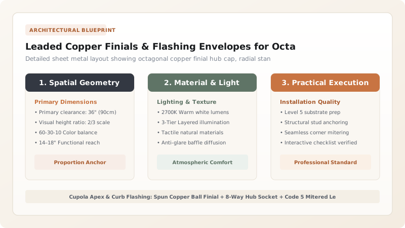
1. Apex Geometry: Eight-Way Converging Hubs & Spun Copper Finials
The apex of an octagonal cupola roof presents one of the most demanding sheet metal geometry challenges in classical architecture. Eight tapered roof pans and eight standing seam hips converge at a single point. Terminating these seams cleanly requires a custom-fabricated Octagonal Copper Hub Cap:
- Eight-Facet Receiving Skirt: Fabricated from \(1.0\text{ mm}\) (24-oz) cold-rolled copper, the hub features eight flared aprons cut to match the roof pitch (typically 45° to 60°). Each apron extends \(150\text{ mm}\) (6 inches) down the roof, terminating in a folded under-hem that locks over the upper ends of the roof pans.
- Metal Spinning Technology: The decorative ball terminal (measuring 200mm to 350mm in diameter) is spun on a lathe from two deep-drawn copper hemispheres, welded or soldered with a continuous lap joint along the equator.
- Turned Architectural Spire: A solid cast or spun copper spire with classical astragal and scotia turnings crowns the ball, secured by an internal \(16\text{ mm}\) stainless steel structural tie rod anchored into the central timber king post.
2. Curb Base Flashing: Code 5 Lead Soakers & 135-Degree Welts
Where the vertical glazed cupola curb intersects the primary pitched roof, rainwater cascades down from higher slopes and splits around the eight polygonal corners. Detailing this intersection requires malleable Code 5 Rolled Sheet Lead (2.24mm / 4.5 lbs/sq ft):
- High-Side Crickets & Saddles: Behind the uphill face of the cupola, a timber cricket diverts runoff around both sides. A seamless 20-oz copper saddle pan with folded and soldered corner dog-ears extends \(200\text{ mm}\) up the curb and \(300\text{ mm}\) under the primary roofing material.
- 135-Degree Polygonal Corner Aprons: Standard 90-degree corner flashing pieces cannot accommodate an octagon. Lead sheets are dressed by hand with boxwood dressers around each 135-degree corner without stretching the lead thinner than \(1.8\text{ mm}\).
- Cover Flashing & Reglet Pockets: A continuous copper counter-flashing apron is notched into a \(25\text{ mm}\) deep saw-cut reglet in the cupola timber sill, folded downward over the lead base flashing, and held with lead wedges at 300mm centers before sealing with non-acidic neutral-cure silicone.
3. Lightning Protection Dynamics: Apex Discharge & Grounding Arrays
Because an octagonal cupola sits at the highest point of a building, its metallic finial is the primary target for direct lightning strikes. Failing to ground this metalwork can result in catastrophic explosive discharge through the timber roof frame.
Architectural lightning protection standards (NFPA 780 / BS EN 62305) require:
The central finial rod acts as a certified Class 1 Air Terminal. A continuous \(50\text{ mm}^2\) bare stranded copper cable is bonded to the bottom of the stainless steel tie rod with an exothermically welded or heavy-duty brass mechanical clamp. The cable runs internally through the building core or concealed down a roof valley to connect to primary copper ground rods driven 3 meters into the earth, achieving an electrical ground resistance of \(<10\,\Omega\). Learn about zinc roofing compatibility in our guide to quartz-zinc versus copper patina physics.
Cupola Flashing Material & Gauge Engineering Guide
Use this reference table to calculate exact physical dimensions, ratios, and specifications before purchasing:
| Flashing Location | Specified Material | Thickness / Code | Joint Execution |
|---|---|---|---|
| Apex Finial Hub Cap | Cold-Rolled Copper (ASTM B370) | 1.0mm (24-oz) Sheet | Full-lap 50/50 tin-lead solder |
| Curb Corner Soakers | Milled Sheet Lead (BS EN 12588) | Code 5 (2.24mm / 4.5 lb) | Bossed / dressed by hand (No solder) |
| High-Side Valley Saddle | Cold-Rolled Copper / Titanium-Zinc | 0.80mm (20-oz Copper) | Fully welded / soldered with dog-ears |
| Sill Counter-Flashing | Pre-Weathered Zinc / Copper | 0.70mm (21 ga Zinc) | Lead-wedged reglet + silicone cap |
| Internal Lightning Conductor | Stranded Electrolytic Copper | 50mm² (1/0 AWG) Cable | Exothermic weld to finial tie-rod |
Metalsmithing & Environmental Constraints
Every successful decoration project must account for physical and environmental constraints:
Lead Bossing Thinning Limits
Dressing lead around acute 135-degree corners can over-thin the metal. The thickness at any stretched point must never fall below 75% of original nominal thickness (\(\ge 1.7\text{ mm}\)).
Capillary Water Creep
Wind pressure drives water upward between overlapping flat sheets of metal. All horizontal laps must incorporate a minimum 100mm lap with continuous folded anti-capillary welt checks.
Thermal Buckling in Large Aprons
Lead or copper flashing strips exceeding 1.5 meters without expansion joints will buckle and split. Restrict individual flashing piece lengths to 1200mm with 100mm slip-laps.
Octagonal Copper Roof & Finial Flashing Sequence
Execute this professional sequence to achieve flawless results without backtracking:
Substrate Membrane & Cleat Installation
Cover double-curved marine plywood cupola roof with high-temperature self-adhering ice-and-water membrane. Install continuous copper starter cleats along the eave cornice.
Tapered Pan Forming & Seam Hemming
Rollform eight tapered copper roof pans, tapering from eave width down to 75mm apex width. Form 25mm double-lock standing seams along the eight hip lines.
Apex Pan Locking & Saddle Soldering
Hook pan lower hems onto eaves cleats. Crimp hip seams. Solder upper pan ends into a watertight perimeter collar 150mm below the timber king post apex.
Octagonal Hub Cap Placement
Slide custom octagonal copper hub cap down over the king post, overlapping the eight roof pans by 150mm. Solder or mechanically lock hub hems to pan ribs.
Finial Spire Erection & Structural Tie-Down
Pass 16mm stainless threaded rod through the turned finial and spun copper ball. Torque base nut to king post, compressing an EPDM sealing gasket.
Lead Corner Dressing & Counter-Flashing
Boss Code 5 lead corner aprons around the eight 135-degree curb base angles. Wedge copper counter-flashings into saw-cut reglet and seal with neutral silicone.
Common Mistakes & Countermeasures
Avoid these costly errors that compromise aesthetics, ergonomics, and budget:
Using Rigid Solder on Long Curb Flashings
Omitting Lightning Protection Bonding
Using Acid Silicone on Copper Reglets
Project Execution Checklist
Track your physical progress. Checkboxes persist automatically on this device:
Frequently Asked Questions
Why is Code 5 lead specified for cupola corners rather than Code 4?
Code 4 lead (1.80mm thick) is standard for simple roof valleys, but the severe multi-plane bossing required to wrap around eight 135-degree polygonal curb corners thins the sheet. Code 5 lead (2.24mm thick) provides the extra metal mass required to ensure corners remain robust, puncture-proof, and durable for over 100 years.
How is a weathervane mounted to the cupola finial?
A high-grade architectural weathervane is mounted on a stainless steel shaft that passes through the copper finial spire into a heavy internal bronze bearing sleeve. The directional compass points (N-S-E-W) are pinned with set screws, and the upper wind-vane arrow rotates freely on low-friction enclosed stainless ball bearings.
Can the copper roof and finial be treated with a dark brown or green patina before installation?
Yes. Custom metalsmiths frequently pre-patinate copper cupola caps using liver of sulfur (for statuary brown) or ammonium chloride solutions (for verdigris green) in the workshop, sealing the finish with microcrystalline wax before hoisting onto the roof.


