
Calculate in-wall cantilever stair stringers by multiplying the 300-lb code design point load by the tread length (e.g. 300 lbs × 3 ft = 900 ft-lbs / 1,220 Nm of bending moment per step). Size the in-wall spine using an 8x8x1/2" HSS structural steel tube with welded 1/2" gusseted outrigger plates, limiting tip deflection to L/500 (<1/16").
At a Glance: Key Takeaways
- Bending Moment Torque Formula: \(M = P \cdot L\) where \(P\) is dynamic tip load (300 lbs) and \(L\) is tread cantilever span.
- Torsional Twist Resistance: Hollow Structural Section (HSS) square tubing provides 40x greater torsional rigidity than standard I-beams.
- L/500 Stringent Deflection Standard: Maximum allowable outer tip bounce is restricted to less than 1.8mm (1/16") for a rock-solid feel.
- Baseplate Chemical Anchor Studs: 3/4-inch heavy Grade 8.8 threaded rods set in structural epoxy anchor the spine into the concrete slab.
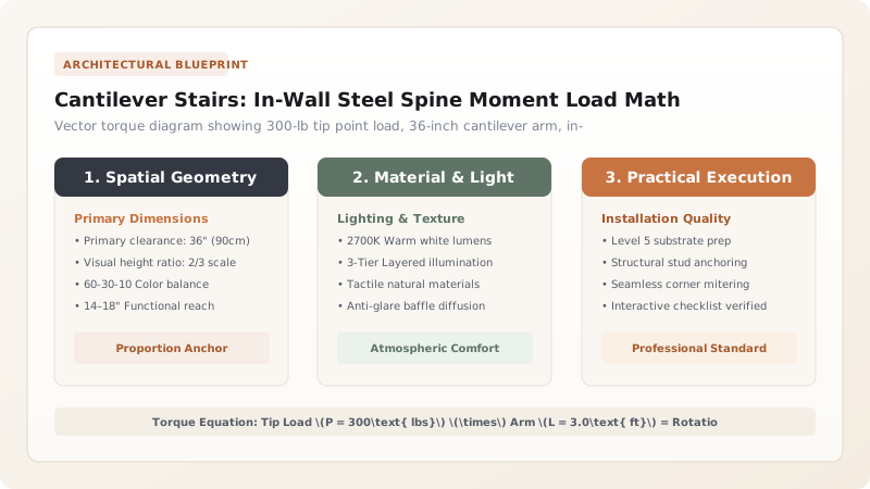
1. Structural Mechanics: Bending Moment & Torsional Shear Stress
When an adult walks down a floating stair, dynamic impact loads reach 1.5x static body weight. For a 200-lb occupant stepping briskly on the outer tip of a 36-inch (0.91m) tread, the dynamic point load is \(P = 300\text{ lbs}\).
The resulting Cantilever Bending Moment is:
$$M = P \cdot L = 300\text{ lbs} \times 3.0\text{ ft} = 900\text{ ft-lbs (1,220 Nm)}$$
Because open I-beams twist easily under torsional shear, engineers mandate Closed Box Sections (HSS 8x8x1/2" Tube), whose closed perimeter resists rotational twisting effortlessly. For tread joinery details, see hardwood box tread miter joinery.

2. Deflection Limits (L/500) & Complete Penetration Groove Welds
Standard architectural floor deflection (\(L / 360\)) feels spongy and terrifying on floating stairs. Floating stair engineering mandates a strict \(L / 500\) Deflection Threshold (less than 1.8mm of tip deflection under load).
Cantilever outrigger blades (1/2" Grade 50 steel plate) must be attached to the HSS tube spine using Full Penetration Groove Welds (CJP Welds) inspected with ultrasonic non-destructive testing. Combine with structural base shoe glass railings.
Tread Cantilever Span vs In-Wall Steel Tube Sizing
Use this reference table to calculate exact physical dimensions, ratios, and specifications before purchasing:
| Tread Cantilever Span (L) | Design Moment Load (M = P·L) | Required Steel Spine Size | Tip Deflection at 300 lbs |
|---|---|---|---|
| 30 Inches (760mm) | 750 ft-lbs (1,017 Nm) | 6" × 6" × 3/8" HSS Tube | 1.2mm (1/32" - Super Rigid) |
| 36 Inches (915mm) Standard | 900 ft-lbs (1,220 Nm) | 8" × 8" × 1/2" HSS Tube | 1.6mm (1/16" - Solid) |
| 42 Inches (1,065mm) Wide | 1,050 ft-lbs (1,424 Nm) | 10" × 10" × 1/2" HSS Tube | 1.9mm (1/16" - Code Compliant) |
| 48 Inches (1,220mm) Grand | 1,200 ft-lbs (1,627 Nm) | 10" × 10" × 5/8" Heavy Tube | 2.2mm (Requires structural PE review) |
Wall Stud Racking Twist Constraints
Every successful decoration project must account for physical and environmental constraints:
Steel Spine Anchored Only to Floor Causing Upper Wall to Sway 1 Inch
If the top of the steel spine is not tied into the upper floor diaphragm, the entire wall flexes like a diving board when walked on; securely weld or bolt the top of the steel spine to a structural steel header beam tied across 3 ceiling joists.
How to Calculate and Specify In-Wall Cantilever Steel
Execute this professional sequence to achieve flawless results without backtracking:
Calculate Maximum Dynamic Moment Load
Multiply 300 lbs point load × tread length (ft) = Moment (ft-lbs) per step outrigger.
Select HSS Steel Tube Section Modulus
Specify 8x8x1/2" HSS tube with section modulus (S) exceeding required bending stress capacity.
Detail Complete Penetration Groove Welds
Specify CJP welds between 1/2" steel outrigger blades and the HSS tube face on shop drawings.
Engineer Concrete Baseplate Anchoring
Detail 1" thick baseplate with four 3/4" Hilti HIT-HY 200 epoxy chemical anchors (minimum 6" embedment).
Anchor Top Spine to Upper Floor Diaphragm
Connect top of steel spine to floor joist header with 1/2" structural steel tie-in brackets.
Common Mistakes & Countermeasures
Avoid these costly errors that compromise aesthetics, ergonomics, and budget:
Using Open C-Channel or I-Beams for the In-Wall Spine
Project Execution Checklist
Track your physical progress. Checkboxes persist automatically on this device:
Frequently Asked Questions
Can a floating cantilever stair be installed in a home with wood floor joists?
Yes! When installing over wood joists, a heavy structural steel transfer beam or doubled LVL beam must be framed into the floor system to support the baseplate of the in-wall steel spine.


