
Engineer coffered ceiling illumination by mounting high-density 24V COB LED tape strips (95+ CRI, warm-dimming 2200K–3000K) inside 45-degree aluminum extrusion channels concealed behind a 1-1/2" dropped crown molding lip. Pair this indirect ambient wash with low-glare 2-inch pinhole architectural downlights centered in beam intersection soffits, powering all fixtures from centralized remote drivers.
At a Glance: Key Takeaways
- Concealed Crown Lip Cove: Dropping the crown molding 1-1/2" down from the ceiling creates an invisible channel for indirect uplighting.
- 45-Degree Aluminum Extrusion Heatsinks: Dissipates LED heat and directs light inward toward the ceiling center at optimal angles.
- Dot-Free COB (Chip-on-Board) LEDs: Eliminates individual visible LED diode reflections on semi-gloss ceiling paint surfaces.
- Beam Soffit Pinhole Downlights: Miniature 2-inch recessed fixtures placed at beam intersections for focused vertical task illumination.
- Centralized Remote Driver Panels: 24V DC transformers located in mechanical closets, eliminating humming drivers overhead and simplifying servicing.
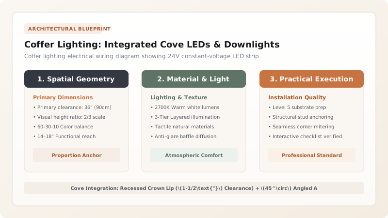
1. Photometric Architecture: The Dropped Crown Lip & 45° Extrusion Angles
Placing LED tape flat on top of a crown molding creates an unsightly hotspot right against the beam cheek, with very little light reaching the center of the coffer panel.
To achieve an even, ethereal Ceiling Photometric Wash, carpenters lower the crown molding by 1-1/2 inches below the ceiling plane. Inside this trough, an Extruded Aluminum Profile angled at 45 degrees directs the light inward toward the center of the coffer. Using a frosted polycarbonate lens diffuses the illumination into a seamless, dot-free gradient. Master box beam joinery in box beam framing and explore plaster-in LED profiles.

2. Fixture Engineering: Beam Pinhole Downlights & Remote Driver Architecture
While cove uplighting creates ambient glow, dining tables and artwork require directional accent illumination.
Hollow box beams are ideally suited for housing Miniature 2-inch Architectural Pinhole Downlights centered at 4-way beam intersections. All fixtures are wired with Class 2 Low-Voltage Homeruns to a central Lutron or 0–10V Dimming Driver Panel in the basement or utility room. This eliminates buzzing AC transformers inside the ceiling and allows flawless smooth dimming down to 0.1%. Master crown trim in interior crown returns and review the coffered ceiling hub.
Coffer Lighting Technology Comparison
Use this reference table to calculate exact physical dimensions, ratios, and specifications before purchasing:
| Lighting Technology | Diode Density / Smoothness | CRI / Color Quality | Heat Dissipation | Visual Glare Control |
|---|---|---|---|---|
| COB (Chip-on-Board) 24V LED Tape (Optimal) | Continuous phosphor (Zero diode dots) | 95+ CRI (True color fidelity) | High (Requires aluminum channel) | 100% Concealed (Zero direct glare) |
| Standard SMD 2835 LED Strip | 60 to 120 LEDs/meter (Visible spotting) | 80 to 90 CRI | Moderate | Spots reflect on semi-gloss ceiling |
| Integrated Neon-Flex Silicone Tube | Continuous diffuse glow | 85 to 90 CRI | Moderate | Bulky profile (Harder to conceal behind trim) |
| Traditional Puck Lights in Coffers (Avoid) | Point-source hot spot | 80 CRI | High localized heat | High direct glare downwards |
Low-Voltage Voltage Drop Over Long Homeruns
Every successful decoration project must account for physical and environmental constraints:
Voltage Drop on 24V LED Tape Causing Far End of Large Ceiling Grid to Dim and Shift Color
Running 24V DC low-voltage lines over 40 feet on thin 18-gauge wire results in a 2-to-3 volt drop, causing the furthest coffer compartments to glow noticeably dimmer; calculate total circuit wattage and install 14-gauge or 12-gauge oxygen-free copper speaker/low-voltage wire feeds connected to both ends of each coffer ring (dual-feed loop).
How to Wire and Install Integrated Coffer Lighting
Execute this professional sequence to achieve flawless results without backtracking:
Run Low-Voltage Class 2 Cables Through Hollow Beams
Pull 14/2 CL2-rated stranded low-voltage wire through hollow beam framing to each coffer compartment before closing soffits.
Install Dropped Crown Molding Leaving 1-1/2" Light Gap
Mount crown molding 1-1/2" below finished ceiling drywall, creating an accessible interior trough.
Fasten 45-Degree Aluminum Extrusion Channels
Screw 45° angled aluminum channels into the rear of the crown lip; clean channel troughs with rubbing alcohol.
Adhere 24V High-CRI COB LED Tape into Channels
Peel 3M VHB thermal adhesive backing; press COB LED strip firmly into aluminum channel; solder lead wire connections.
Snap Frosted Polycarbonate Diffuser Lenses into Extrusions
Install frosted lenses over aluminum channels to protect diodes from dust and eliminate specular diode reflections.
Hole-Saw Beam Soffits for 2" Pinhole Downlights
Use carbide hole saw to core 2-1/4" openings at beam intersections; wire low-voltage LED downlight modules.
Commission Central Dimming Panel and Set Warm-Dim Curves
Connect circuits to remote Lutron Hi-lume or 0-10V drivers; program dimming scenes to warm color temperature down to 2200K at night.
Common Mistakes & Countermeasures
Avoid these costly errors that compromise aesthetics, ergonomics, and budget:
Sticking LED Tape Directly to Raw Wood Without Aluminum Channels
Project Execution Checklist
Track your physical progress. Checkboxes persist automatically on this device:
Frequently Asked Questions
What color temperature is best for coffered ceiling cove lighting?
A warm-dimming LED engine (3000K fading to 2200K or 1800K) is optimal. At full output, 3000K renders crisp white architectural details; when dimmed down for dinner or entertaining, it shifts to rich golden candlelight tones.


