
Conceal 24V LED under-cabinet drivers by mounting them in three professional locations: 1) On the top interior shelf of an upper cabinet (inside a junction box), 2) Inside a nearby walk-in pantry closet, or 3) In a central basement utility panel. Use Class 2 in-wall rated 18/2 wire.
At a Glance: Key Takeaways
- National Electrical Code (NEC): Drivers and junction boxes must remain permanently accessible (never bury behind drywall).
- Top Cabinet Shelf: Most popular location; hidden from sight on top shelf behind cereal or serving platters.
- Central Pantry Panel: Simplifies multi-zone control by placing drivers for under-cabinet, cove, and island lights together.
- Class 2 Low-Voltage Wire: 18AWG in-wall CL2 rated wire can safely route through cabinet backs without conduit.
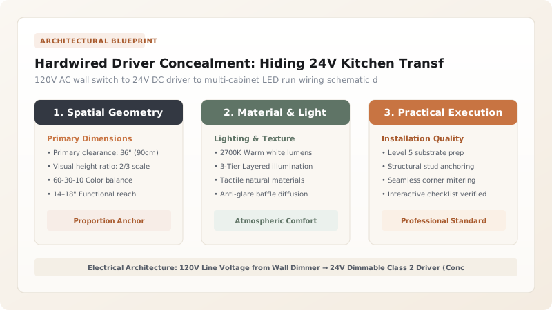
1. NEC Electrical Code & The Accessibility Mandate
National Electrical Code (NEC Article 450.13) strictly mandates that all transformers, power supplies, and junction boxes must remain accessible for inspection and maintenance without removing permanent building structures. Burying a 24V driver inside a sealed drywall wall cavity violates electrical code and creates a serious fire hazard.
Professional kitchen electricians run 120V switch-leg power to a designated top cabinet shelf, above the refrigerator enclosure, or inside a pantry closet, where the metal-enclosed Class 2 driver is securely mounted and ventilated.

LED Driver Concealment Locations Comparison
Use this reference table to calculate exact physical dimensions, ratios, and specifications before purchasing:
| Concealment Location | Accessibility | Installation Complexity | Ventilation & Cooling |
|---|---|---|---|
| Top Shelf of Upper Cabinet | 100% Accessible (Open door) | Low (Drill small 1/4" floor hole) | Good (Ample air volume in cabinet) |
| Above Refrigerator Enclosure | 100% Accessible (Step stool) | Low (Hidden behind top panel) | Excellent (Open chimney airflow) |
| Inside Walk-In Pantry Closet | 100% Accessible (Dedicated panel) | Moderate (Pull low-voltage wire) | Maximum (Cool ambient room temp) |
| Basement / Utility Room | 100% Accessible (Main panel) | High (Long wire runs from basement) | Maximum (Zero kitchen noise) |
Low-Voltage Long Distance Voltage Drop Constraints
Every successful decoration project must account for physical and environmental constraints:
Placing Driver 50 Feet Away in Basement Causing LEDs to Dim
Running thin 20AWG wire 50 feet causes low-voltage DC resistance and dimming; if drivers are located in the basement, strictly use heavier 14AWG or 16AWG in-wall CL2 rated copper wire to maintain a full 24.0 Volts at the kitchen counter.
How to Wire and Conceal a 24V Kitchen Driver
Execute this professional sequence to achieve flawless results without backtracking:
Rough-In 120V Romex to Top Cabinet
Pull 14/2 Romex from kitchen wall dimmer switch up to the top shelf of the upper cabinet.
Mount UL-Listed Class 2 Driver
Screw metal driver enclosure to the back wall of the top cabinet shelf.
Connect 120V AC Input
Wire Black (Hot), White (Neutral), and Green (Ground) to AC terminal block.
Route 18/2 Low-Voltage Down
Drill a discreet 1/4" hole in the corner of the cabinet floor and route 18/2 wire down to the LED strip.
Verify Forward-Phase Dimming
Test wall dimmer; adjust low-end trim wheel on dimmer switch to eliminate buzzing.
Common Mistakes & Countermeasures
Avoid these costly errors that compromise aesthetics, ergonomics, and budget:
Using Non-Dimmable Drivers with Standard Wall Dimmer Switches
Project Execution Checklist
Track your physical progress. Checkboxes persist automatically on this device:
Frequently Asked Questions
What size driver wattage do I need for my kitchen under-cabinet lighting?
Multiply total feet of LED tape by watts-per-foot, then add a 20% safety buffer. For example: 16 feet × 4.5 Watts/ft = 72 Watts. Select a 96-Watt or 100-Watt 24V driver.


