
A double-lock standing seam is formed by folding adjacent 35mm male and 45mm female sheet metal flanges into an initial 90-degree angle lock, followed by a secondary 90-degree fold downward to create a finished 25mm (1-inch) high continuous mechanical interlock. Stainless steel two-piece expansion clips hooked inside the seam provide 70mm of sliding travel, resisting wind suction while allowing unrestricted thermal movement along the pitch.
At a Glance: Key Takeaways
- Finished Profile Height: Standard 25mm (1.0 inch) provides architectural shadow lines and high resistance to driving rain and snow drifts.
- Sheet Width Optimization: Standard coil widths of 500mm and 650mm produce finished pan widths of 430mm (17 inches) and 580mm (23 inches).
- Two-Piece Clip Construction: Grade 304 stainless steel 0.5mm base tab anchored to deck with a sliding 0.5mm upper shoe crimped into the seam.
- Wind Uplift Load Resistance: Tested pull-out resistance exceeding 1.8 kN per clip when anchored with dual stainless torx fasteners into 22mm timber.
- Mechanical Seaming Sequence: Motorized 4-roller profiling machines crimp angle fold at stage 1 and final double lock fold at stage 2.
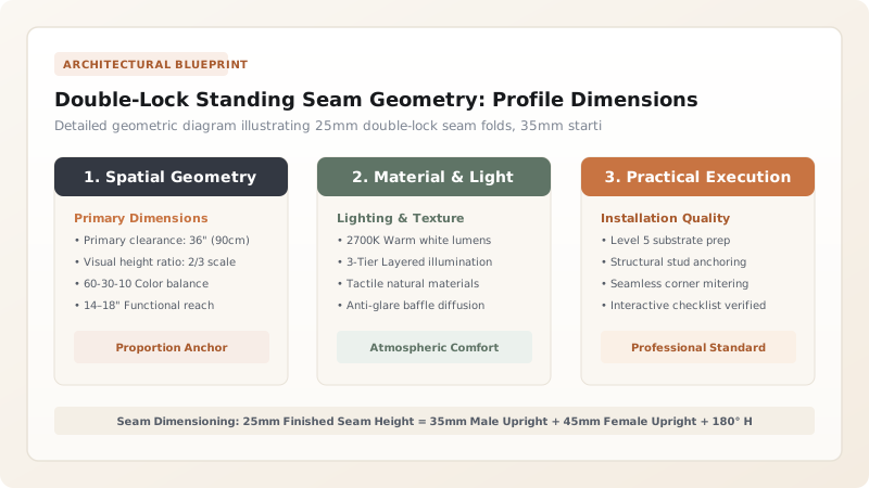
1. Precision Flange Geometry: Upright Fold Measurements & Tolerances
Forming an airtight, watertight double-lock seam requires micro-millimeter precision during pan rollforming. The two lateral edges of each sheet metal tray are pre-formed with asymmetric flanges:
- Male Upstand (Small Flange): Height of \(35\text{ mm}\) folded upward at 90 degrees with a 135-degree return hem of \(7\text{ mm}\) at the lip.
- Female Upstand (Large Flange): Height of \(45\text{ mm}\) folded upward at 90 degrees with a 180-degree reverse hem of \(15\text{ mm}\) that caps over the male flange.
When placed adjacent on the roof deck, the female hem caps over the male flange and the hooked head of the stainless steel clip. During first-pass mechanical seaming, the flanges are folded 90 degrees into an Angle Standing Seam. The second pass bends the folded package another 90 degrees flat against the upstand, producing the finished \(25\text{ mm}\) (1.0 inch) double-lock profile.
Relief clearances of \(0.5\text{ mm} \text{ to } 1.0\text{ mm}\) inside the folded radii ensure the metal is not crimped into plastic shear failure, preventing micro-fissuring along the outer bend radius.
2. Clip Mechanics: Sliding Resistance, Anchor Torque & Wind Uplift
Standing seam roofs rely entirely on concealed clips for structural attachment. The engineering dynamics must balance two diametrically opposed structural demands: Shear Sliding Freedom (parallel to the seam) and Tensile Pull-Out Rigidity (perpendicular to the deck under negative wind suction pressure).
A high-performance architectural sliding clip consists of:
- Base Plate: Stamped 1.0mm 304-grade stainless steel with two countersunk screw holes and flared guide rails.
- Sliding Hook Tab: 0.6mm stainless steel shoe with a hooked top edge crimped inside the seam. The shoe travels smoothly along a \(70\text{ mm}\) linear channel.
- Frictional Resistance: Maximum sliding friction must not exceed \(50\text{ N}\) per clip under ambient temperature shifts, preventing buckling ripples across wide pans.
Fasteners must be \(4.5\text{ mm} \times 35\text{ mm}\) passivated stainless steel woodscrews with flat pan heads countersunk flush with the base plate to avoid puncturing the underside of the sheet metal tray.
3. Pan Width Engineering: Minimizing Oil-Canning Distortions
Oil-canning—the aesthetic visual rippling or buckling across flat metal pans—is caused by thermal expansion stress, uneven sub-deck planarity, or excessive rollformer forming pressure. To mitigate oil-canning:
- Limit Pan Widths: Avoid wide 650mm coil widths on steep visible slopes. Standardize on \(430\text{ mm}\) (17 inch) pan centers rollformed from 500mm coils.
- Crown Pre-Tensioning: High-end rollformers introduce a subtle convex transverse crown of \(0.8\text{ mm}\) into the flat pan, pre-stressing the metal outward so that thermal expansion relieves internal tension smoothly rather than snapping into concave oil-cans.
- Substrate Stiffness: Ensure tongue-and-groove timber boards have maximum moisture content of \(\le 14\%\) at installation to prevent post-installation shrinkage from warping clip anchor planes. Learn patina characteristics in our guide to pre-weathered quartz-zinc versus copper.
Standing Seam Profile Specification & Fastener Guide
Use this reference table to calculate exact physical dimensions, ratios, and specifications before purchasing:
| Seam Type / Metric | Single-Lock Angle Seam | Double-Lock Standing Seam | Snap-Lock Standing Seam |
|---|---|---|---|
| Finished Seam Height | 25mm (1.0 inch) | 25mm or 32mm (1.0 or 1.25 in) | 25mm - 38mm (1.0 - 1.5 in) |
| Min Slope Requirement | 25° (approx 5.5:12 pitch) | 3° (approx 5/8:12 pitch) | 14° (approx 3:12 pitch) |
| Weathertightness Index | High (Gravity draining) | Maximum (Hermetic capillary break) | Moderate (Gasketed snap-cap) |
| Required Tooling | Hand tongs or 1-stage crimper | Dual-stage motorized seamer | Hand snap / mallet tapping |
| Sliding Clip Suitability | Excellent | Mandatory for runs >3m | Integrated screw-slot relief |
| Primary Architectural Application | Mansard roofs, facades, steep gables | Low-pitch roofs, complex dormers | Commercial utility, simple sheds |
Field Forming & Tooling Constraints
Every successful decoration project must account for physical and environmental constraints:
Bend Radius Metal Fatigue
Bending zinc with sharp zero-radius tooling causes microscopic grain fracture. Inside bend radii must always be equal to or greater than the metal sheet thickness (\(R \ge 1.0 t\)).
Fastener Head Clearance
Screws with protruding bugle heads push upward against the bottom of the tray pan, creating visible dimples along every clip location. Use strictly flush-countersunk torx drive screws.
Excessive Seamer Roll Pressure
Over-tightening seaming machine compression rollers crushes the sliding shoe, locking it to the base plate and eliminating all thermal movement capability.
Precision Double-Lock Seaming Sequence
Execute this professional sequence to achieve flawless results without backtracking:
Tray Pan Alignment & Cleat Engagement
Hook the lower hem of tray 1 onto the eaves starter cleat. Align tray 1 parallel to the gable verge using chalk lines spaced exactly at 430mm.
Clip Distribution & Anchor Torquing
Insert sliding clip shoes into the male upstand flange at 350mm centers. Drive two stainless countersunk screws per clip into timber boards at 4.0 Nm torque.
Adjacent Tray Mating
Slide tray 2 over tray 1, capping the 45mm female upstand over both the 35mm male flange and the internal stainless clip shoes.
Tack Crimping & Position Lock
Use manual hand closing tongs every 1.5 meters along the seam to tack-crimp the joint, preventing wind uplift before motorized rolling.
Motorized Angle Seam Roll Pass (Stage 1)
Engage electric seamer equipped with stage 1 rollers. Run seamer from eaves to ridge at 12 m/min to bend the 45mm flange 90 degrees over the male edge.
Motorized Double Lock Pass (Stage 2)
Switch seamer to stage 2 rollers. Run from ridge down to eaves to complete the final 180-degree wrap, verifying seam height at 25mm.
Common Mistakes & Countermeasures
Avoid these costly errors that compromise aesthetics, ergonomics, and budget:
Running Seamers in Wrong Direction
Using Galvanized or Zinc-Plated Screws
Over-Crimping Sliding Shoes
Project Execution Checklist
Track your physical progress. Checkboxes persist automatically on this device:
Frequently Asked Questions
Can double-lock standing seam profiles be formed on curved barrel roofs?
Yes. Architectural zinc and copper standing seams can be curved down to a concave radius of 2.0 meters and convex radius of 1.5 meters using specialized rotary stretch-curving machines that gently stretch or compress the vertical seam uprights without wrinkling the pan.
Why is 25mm the standard standing seam height instead of 38mm or 50mm?
A 25mm (1-inch) seam strikes the perfect architectural balance: it provides an impenetrable capillary barrier against standing water while maintaining sufficient flexibility for tight radius curves, hand-folded ridge roll transitions, and elegant low-profile residential aesthetics.
How much pull-out resistance is required per clip?
Under building code ASCE 7 and European standards (EN 1991), edge and corner roof zones require minimum clip pull-out resistance of 1.5 kN to 2.2 kN, achieved by fastening into minimum 22mm solid timber boarding with two #8 stainless screws per clip.


