
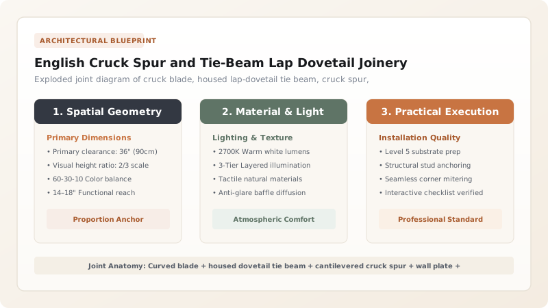
English Cruck Spur and Tie-Beam Lap Dovetail Joinery forms the structural nexus that locks curved cruck blades into a rigid transverse arch. Located across the middle span of the blades, the heavy horizontal tie beam is secured using barefaced lap dovetail joints housed directly into the timber faces. Crucially, horizontal cantilevered timber ties called cruck spurs project outward from the blades to connect with external wall-plates, anchoring the building's outer envelope and preventing outward roof spread.
At a Glance: Key Takeaways
- Barefaced Lap Dovetail: One-sided flared dovetail joint resisting extreme horizontal tension forces across the frame.
- Cruck Spurs (Wall-Ties): Short horizontal timber brackets locking the curved blades to outer vertical wall-posts.
- Housed Shoulders: Sinking the joint 25mm into the blade body to prevent vertical downward slipping under roof dead loads.
- Draw-Bored Trenail Pegs: Oak dowels driven through misaligned holes to pull joint shoulders tight like a heavy vise.
- Tensile Integrity: Neutralizing outward roof thrust without relying on brittle iron fasteners or nails.
1. Tensile Mechanics of the Barefaced Lap Dovetail
In a heavy timber roof, the horizontal tie beam is subjected to enormous axial tension as the weight of heavy stone slates or thatch pushes the rafter feet outward. In medieval framing, mortise-and-tenon joints could fail under tension because the thin wooden pin (peg) would shear along its grain.
To solve this, English carpenters perfected the barefaced lap dovetail (or half-dovetail). The end of the tie beam is cut with a single 1:6 flared dovetail wedge that drops into a matching housing carved into the face of the cruck blade. Because the flare widens toward the outer end, outward tension forces physically pull the dovetail tighter into its housing, preventing joint separation.
2. Cruck Spurs: Connecting the Arch to the Wall Envelope
Because curved cruck blades bow inward toward the interior of the barn, they sit anywhere from 300mm to 900mm away from the plane of the exterior side walls. To brace the outer walls and carry the heavy horizontal wall plates (which support common rafters), carpenters inserted cruck spurs (or spur ties).
The cruck spur is a sturdy horizontal timber measuring 150mm x 200mm. Its inner end is mortised or half-lapped into the cruck blade, while its outer end is mortised into the vertical wall post or notched under the wall plate, creating a rigid triangular truss at the eaves.
3. Upper Bracing: Collar Beams and Apex Yokes
Above the main tie beam, cruck frames incorporate secondary upper horizontal members. At roughly two-thirds height, a collar beam prevents the upper rafter tips from sagging inward.
At the apex, where the two curved blades converge, carpenters utilized several historical solutions: an apex yoke (a short horizontal collar supporting a square ridge-piece), a saddle (a notched block perched across the tips), or a direct halved lap joint, allowing the ridge tree to rest securely in the V-shaped crotch.
Cruck Frame Structural Joinery Specifications
Use this reference table to calculate exact physical dimensions, ratios, and specifications before purchasing:
| Joint Location | Joint Typology | Housing Depth (mm) | Fastening Method | Primary Mechanical Stress |
|---|---|---|---|---|
| Tie Beam to Blade | Barefaced Lap Dovetail with 1:6 flare | 25mm - 35mm housed | 2 x 22mm Cleft Oak Pegs | Horizontal Axial Tension |
| Cruck Spur to Blade | Housed Lap or Through-Mortise | 20mm - 30mm housed | 1 x 20mm Cleft Oak Peg | Transverse Compression & Shear |
| Spur to Wall Plate | Cogged Lap or Mortise & Tenon | 25mm cogged seat | 1 x 18mm Heartwood Peg | Lateral Racking & Vertical Dead Load |
| Collar Beam to Blade | Half-Lap or Stub Mortise | 20mm housed | 2 x 20mm Cleft Oak Pegs | Compression & Arch Bracing |
Joinery & Sizing Constraints
Every successful decoration project must account for physical and environmental constraints:
Shrinkage Along the Dovetail Flare
Tangential shrinkage of green oak can loosen the dovetail wedge over 2 years unless draw-bored with dry pegs.
Timber Cross-Grain Weakness
Chopping deep housings into curved blades reduces their effective structural bending depth; housing depth must not exceed 15% of blade thickness.
Protocol for Laying Out and Cutting a Housed Lap Dovetail Joint
Execute this professional sequence to achieve flawless results without backtracking:
Tie Beam Sizing & Shoulder Layout
Square green oak tie beam to 220mm x 280mm; mark outer shoulder cut lines across both ends using framing square.
Dovetail Flare Scribing (1:6 Ratio)
Lay out single-sided dovetail flare on beam end with 1:6 taper; cut back cheeks with crosscut saw and broad chisel.
Overlying Transfer Scribing
Lay prepared tie beam end directly over cruck blade; scribe around dovetail perimeter into blade face with sharp race knife.
Blade Housing Chopping
Chisel housing 25mm deep into blade face; undercut rear wall 2° to ensure snug seating of dovetail wedge.
Draw-Boring Offset Hole Drilling
Drill 22mm hole through assembled joint; remove beam; drill hole through tenon offset 3mm toward joint shoulder.
Pin Driving & Joint Clamping
Re-seat tie beam in housing; drive tapered dry cleft oak peg with wooden beetle; the offset hole draws joint tight.
Common Mistakes & Countermeasures
Avoid these costly errors that compromise aesthetics, ergonomics, and budget:
Cutting the dovetail taper on both sides of the tie beam (double dovetail)
Failing to house the dovetail shoulder into the cruck blade face
Project Execution Checklist
Track your physical progress. Checkboxes persist automatically on this device:
Frequently Asked Questions
What is draw-boring in timber framing?
Draw-boring is the practice of drilling the peg hole through the mortise cheek, inserting the tenon, and drilling the hole through the tenon approximately 3mm closer to the shoulder. When a tapered oak pin is driven through, it forces the holes into alignment, pulling the joint shoulder tight with thousands of pounds of clamping force.
Why are cleft oak pegs better than modern turned dowels?
Cleft pegs are hand-split along the natural grain of heartwood oak using a froe, ensuring 100% continuous wood fibers. Machine-turned dowels cut across the grain (grain runout), causing them to snap easily under shear stress.


