
Dutch windmill and watermill framing centers on the achtkant—a truncated octagonal pyramidal bent cage constructed from eight massive European oak corner posts (hoekstijlen) interlocked with horizontal bintbalken and diagonal sway braces. Heavy cross-girders (kruisbalken) span the central core to support multi-ton millstones, pit wheels, and windshaft bearings. All structural connections rely on traditional heavy timber joinery: mortise-and-tenons secured by tapered draw-bore oak trunnels, under-squinted stop-scarf joints to extend towering corner posts, and double-notched lap joints that dissipate dynamic rotational resonance without steel plates.
At a Glance: Key Takeaways
- Connection Hardware: Tapered hand-hewn oak trunnels (Toognagels, 25-32mm diameter)
- Corner Post Dimensions: 300x300 mm to 400x400 mm solid European oak heartwood
- Framing System: Octagonal timber bent cage (Achtkant structural framework)
- Inward Batter Angle: 78 to 82 degrees for aerodynamic stability and base shear transfer
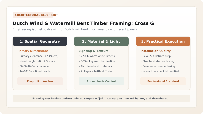
The Achtkant Geometry: Aerodynamic Batter and Dynamic Wind Resistance
Unlike static timber-framed houses, a Dutch windmill or heavy watermill is a dynamic kinetic machine subject to violent, fluctuating torsional forces. The primary framing system is the achtkant (eight-sided polygon). By angling the eight primary corner posts inward at an 80-degree slope, millwrights achieved two critical mechanical goals: establishing a wide, tip-resistant ground footprint and creating an aerodynamic conical form that sheds turbulent North Sea gusts without creating destructive lee-side eddies.
The eight corner posts sit upon heavy brick or granite footing blocks via massive oak foundation sills (onderbalken). At each intermediate floor level—the grain floor, stone floor, and dust floor—rigid polygonal ring collars (kuipbanden) encircle the posts, locking them in permanent compressive hoop tension.
Heavy Cross-Girders (Bintbalken) and Harmonic Damping
A pair of grinding millstones can weigh between two and four metric tons and spin at up to 120 revolutions per minute. Transmitting this massive rotating mass requires exceptional structural rigidity. Millwrights bridged the interior octagonal spans with heavy cross-girders (kruisbalken), sized up to 450x350 mm in cross-section.
These beams are positioned in perpendicular cross-tiers, notched into one another with keyed cog joints. The natural fibrous elasticity of green-sawn European oak provides critical mechanical damping, absorbing micro-vibrations and shock impacts when sails catch sudden storm squalls, preventing harmonic resonance from shaking the timber framework apart.
Master Joinery: Under-Squinted Scarf Joints and Draw-Bore Trunnels
Because 18-meter-tall straight oak trunks were rare and expensive even in the 17th century, millwrights developed sophisticated timber splicing methods. Vertical corner posts were extended using the under-squinted halved stop scarf joint (haaklas met borst en wig). This joint incorporates opposing 45-degree bearing shoulders and a central hardwood driving wedge that pre-stresses the splice against bending moments.
All mortise-and-tenon joints in the frame are locked using the draw-boring technique. The hole drilled through the mortise cheek is intentionally offset by 3 to 4 mm from the hole through the tenon tongue. When a tapered dry oak peg (toognagel) is hammered through, it forces the joint into immense mechanical tension, pulling the timber shoulders rock-tight against the posts.
Heritage Millwright Maintenance and Timber Conservation
Restoring historic Dutch mill framing demands strict adherence to historic wood species and moisture regimes. Replacing rotten lower post sections is accomplished through prosthetic under-pinning: the multi-ton mill superstructure is supported on temporary hydraulic steel jacks while rotten timber bases are cut away with chain saws and replaced with matching air-seasoned heartwood oak dutchman splices.
Modern epoxy consolidants are avoided in primary structural junctions because they trap internal moisture behind impermeable synthetic barriers. Instead, historic millwrights apply hot linseed oil mixed with pine tar and lampblack to repel rain while allowing the massive heartwood timbers to breathe across seasonal humidity swings.
Dutch Mill Bent Joinery & Structural Component Matrix
Use this reference table to calculate exact physical dimensions, ratios, and specifications before purchasing:
| Structural Member | Minimum Section (mm) | Dominant Stress Mode | Joinery Specification | Fastener Protocol |
|---|---|---|---|---|
| Achtkant Corner Posts | 350 x 350 | Combined compression & bending | Under-squinted stop scarf with central key | Double 28mm dried oak trunnels |
| Stone Floor Cross-Girders | 400 x 300 | High dynamic flexural bending | Cogged lap joint into corner posts | Tapered draw-bore trunnel pins |
| Windbrace Struts (Kruisschoren) | 200 x 150 | Alternating tension & compression | Blind mortise-and-tenon with 50mm relish | Single draw-bored trunnel |
| Cap Kerb Ring (Kruiwerk) | 300 x 250 (curved) | Horizontal shear and rotational friction | Segmented lap scarf with iron flanged guide | Recessed counter-sunk bronze lag bolts |
Practical Constraints
Every successful decoration project must account for physical and environmental constraints:
Massive Overturning Moments Under Sudden Gale-Force Gusts
Unanchored corner posts can lift off brick piers during severe North Sea storms, causing catastrophic mill collapse. Solution: Anchor bottom sill tie-beams into foundation brickwork with deep internal wrought-iron tie rods equipped with threaded turnbuckles.
Scarcity of Long Clear-Spanned Structural Oak Timbers
Modern restoration projects cannot source 15-meter single-stick oak logs without defect knots and grain runout. Solution: Engineer traditional multi-segment spliced posts using authenticated 17th-century under-squinted stop scarf joints in premium grade oak.
Execution Blueprint & Craftsmanship Sequence
Execute this professional sequence to achieve flawless results without backtracking:
Framing Yard Template Layout (Molenmakersvloer)
Snap full-scale chalk layout lines of the 8-sided bent on the framing floor; scribe angles directly onto seasoned oak balks.
Corner Post Scarf Joint Fabrication
Hew matching under-squinted scarf joints on post segments using framing chisels and rip handsaws; test-fit central hardwood locking wedge.
Mortise-and-Tenon Cutting and Draw-Bore Offset
Chisel mortises into corner posts; bore trunnel holes through mortise cheeks, then drill tenon holes offset 3.5mm toward shoulder.
Ground Pre-Assembly and Bent Squaring
Pre-assemble two opposing bents on the ground; drive temporary iron hook-pins (ritsijzers) to check diagonals and plumb lines.
Mill Raising (Oprichten) with Gin Poles and Tackles
Erect assembled bents sequentially onto brick sills using shear legs and block-and-tackle winches; immediately brace with temporary sway poles.
Permanent Trunnel Driving and Collar Locking
Replace iron pins with dried octagonal oak trunnels lubricated with beeswax; drive home and wedge cross-girder bintbalken collars.
Common Mistakes & Countermeasures
Avoid these costly errors that compromise aesthetics, ergonomics, and budget:
Omitting the 3mm Draw-Bore Hole Offset in Tenon Joinery
Rigid Steel Plating Across Timber Scarf Joints
Project Execution Checklist
Track your physical progress. Checkboxes persist automatically on this device:
Frequently Asked Questions
Why did Dutch millwrights favor octagonal timber frames over square frames?
An eight-sided octagonal structure distributes wind pressure far more evenly than a square box. By presenting oblique angles to incoming winds from any quadrant, the octagonal shape halves the wind resistance surface area and eliminates the massive localized racking stresses common in rectangular timber towers.
What is the purpose of the draw-bore offset in oak pegging?
Draw-boring creates permanent mechanical spring tension in the joint. By intentionally drilling the tenon hole slightly closer to the shoulder than the mortise cheek holes, driving a tapered oak trunnel forces the tenon tongue inward, locking the shoulders together under tons of continuous compressive clamping force.
How long do the main structural oak timbers of a Dutch windmill last?
When properly maintained and protected by thatched reed walls or weatherboarding, European heartwood oak frames frequently survive over 300 to 400 years. Timbers only deteriorate if roof thatch leaks go neglected or water leaks into foundation sills.
Can green unseasoned oak be used for mill framing?
Yes, historic millwrights predominantly framed with green or partially seasoned oak. Green oak is significantly easier to hand-hew and chisel. Because draw-bore pegged joints are designed to accommodate shrinkage, the timbers lock even tighter together as the oak seasons in place.


