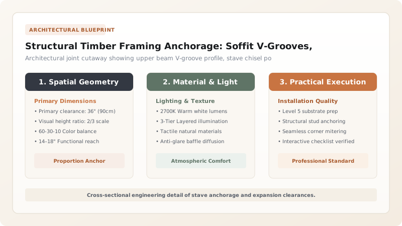
Anchoring wattle infill panels into an oak timber frame requires specific traditional carpentry joinery that accommodates frame deflection without dislodging the infill. Carpenters cut a continuous 20 mm wide by 25 mm deep V-groove or rectangular channel along the underside (soffit) of the upper timber beam. Directly below on the sill beam, matching 25 mm diameter blind auger sockets are bored 30 mm deep, spaced 200–250 mm apart. Cleft oak or ash staves are cut slightly longer than the clear bay height, tapered into a chisel point at the top and rounded at the bottom. By inserting the top into the upper groove, bowing the stave outward, and snapping the lower tenon into the sill socket ('springing the stave'), the upright locks firmly into position under perpetual tension without iron fasteners.
At a Glance: Key Takeaways
- Upper Beam Joinery: Continuous V-groove or trench (20 mm wide x 25 mm deep)
- Lower Sill Joinery: Bored blind auger holes (25 mm diam. x 30 mm deep)
- Stave Spacing: 200 to 250 mm center-to-center along timber bay
- Anchorage Mechanism: Elastic stave springing under longitudinal compression
- Fastener Type: 100% all-wood friction fit; zero metal nails or screws
- Movement Allowance: Up to 15 mm vertical timber shrinkage without panel buckling
The Soffit Groove & Blind Auger Socket Architecture
In traditional English box-frame construction, infill panels are never nailed directly to timber faces. Instead, carpenters engineered an ingenious interlocking groove-and-socket system during the initial fabrication of the frame on the rearing ground. On the underside (soffit) of the upper horizontal tie beam or mid-rail, a continuous groove (the run-groove) is chopped with a riving chisel. This groove is typically 20 to 25 mm wide and 25 to 35 mm deep, featuring chamfered lips to facilitate stave insertion.
Directly beneath on the top face of the bottom sill beam, the carpenter uses a T-handled auger to bore a series of blind circular holes 25 mm in diameter and 30 mm deep. These sockets are spaced systematically at 200 to 250 mm intervals. By combining a continuous channel at the top with individual sockets at the bottom, the structure allows individual staves to be slid, adjusted, and locked into place without disassembling the timber frame.
The Physics of Springing Cleft Staves Under Tension
Installing the vertical staves relies on the natural elasticity of green cleft timber. A stave is carved from cleft oak or ash with a cross-section of approximately 30 by 40 mm. The top end is shaped into a wedge-like chisel edge, while the bottom is whittled into a cylindrical peg matching the sill auger socket. Crucially, the total length of the stave is cut 15 to 20 mm longer than the clear vertical opening between the upper groove floor and the lower sill face.
To install, the carpenter inserts the tapered upper end deep into the upper soffit groove. The middle of the supple stave is then forcibly bowed outward into an arc. As the stave flexes, its overall vertical dimension shortens, allowing the lower rounded peg to slip over the sill edge and align directly over the auger socket. When released, the stave snaps straight with a resounding crack, its lower peg seating securely into the socket while the top remains captive within the groove. This pre-stressed tension locks the stave firmly against lateral wind loads while leaving vertical clearance in the groove to accommodate future frame settlement.
Lateral Racks, Stud Rebates, & Edge Keying
At the vertical boundaries of each bay—against the heavy oak corner posts and intermediate studs—anchorage must prevent separation cracks between timber and daub. Historical carpenters employed two techniques: side grooving and chiseled rachets.
In high-status frames, vertical grooves matching the upper soffit channel were cut down the sides of the studs. In simpler vernacular structures, carpenters cut angled notches (rachets or ledges) every 150 mm into the inner faces of the vertical studs. The ends of the woven horizontal hazel withies were driven directly into these notches. When wet daub was pressed into the bay, it locked into the notches, preventing wind-driven rain from penetrating the perimeter junction between the earthen panel and the timber framing.
Stave Anchorage Methods in Historical Timber Frames
Use this reference table to calculate exact physical dimensions, ratios, and specifications before purchasing:
| Anchorage Method | Upper Beam Detail | Lower Sill Detail | Suitability / Period |
|---|---|---|---|
| Continuous Groove & Auger Sockets | 25 mm continuous V-groove | 25 mm bored blind auger holes | Standard medieval & Tudor box-frame construction |
| Dual Continuous Grooves | 25 mm continuous groove | 15 mm shallow groove | Later 16th-17th century panels; allows rapid assembly |
| Chiseled V-Notches (Stave Holes) | Staggered chiseled V-pockets | Matching blind mortises | Early medieval cruck frames and barns |
| Drilled Auger Holes Top & Bottom | Individual auger holes | Individual auger holes | Requires cutting staves in half or extreme bending |
Practical Constraints
Every successful decoration project must account for physical and environmental constraints:
Distorted and Settled Historic Oak Timbers
Ancient timber bays are rarely square or plumb, requiring custom stave lengths for every individual position in a single panel. Mitigation: Measure each stave individually from groove floor to sill face, numbering staves consecutively across the bay.
Execution Blueprint & Craftsmanship Sequence
Execute this professional sequence to achieve flawless results without backtracking:
Marking Spacing on Timber Members
Mark stave centerlines at 200 to 250 mm intervals along the sill beam and transfer directly to the upper beam soffit using a plumb bob.
Chiseling Continuous Channel
Score guide lines with a timber mortise gauge. Chisel a clean, continuous channel 20 mm wide and 25 mm deep with chamfered entrance lips along the upper beam.
Drilling Blind Auger Holes
Bore 25 mm diameter blind sockets 30 mm deep into the sill plate at marked centers using a hand auger or spade bit with depth stop.
Tension-Fitting Cleft Uprights
Carve stave top to a chisel edge and bottom to a round peg. Insert top into upper groove, bend the stave outward into an arc, and snap the bottom peg into the sill socket.
Common Mistakes & Countermeasures
Avoid these costly errors that compromise aesthetics, ergonomics, and budget:
Fastening Staves with Rigid Modern Iron Screws or Nails
Cutting Staves Too Short Without Expansion Clearance
Project Execution Checklist
Track your physical progress. Checkboxes persist automatically on this device:
Frequently Asked Questions
What is the primary advantage of springing staves over nailed laths?
Springing staves creates a pre-stressed timber lattice that relies purely on friction and elastic tension. When green oak beams deflect under seasonal weight and moisture variations, the staves slide microscopically within the upper groove without detaching or splitting the panel.
Can round branches be used as staves instead of cleft timber?
Round branches retain their bark, which harbors wood-boring insects and shrinks away from the wood, creating hollow channels inside the daub. Cleft timber removes bark entirely and exposes tough heartwood that bonds permanently with the clay.