
Automate cascading stair lighting by installing a multi-channel LED step sequencer controller board (supporting 16 to 32 outputs). Position concealed PIR motion sensors at the top and bottom risers, wire individual 20/2 AWG homeruns from each step to the controller, and program a 0.3-second delay between steps with a 30-second hold time.
At a Glance: Key Takeaways
- Directional Footstep Tracking: Walking upward triggers steps 1 through 16 sequentially; walking downward triggers steps 16 down to 1.
- Dedicated Step Homerun Wiring: Every single tread requires its own dedicated 2-wire low-voltage pair back to the controller board.
- Pulse-Width Modulation (PWM) Soft-Fading: Smooth 300ms fade-in and fade-out transitions eliminate abrupt, jarring light clicks.
- Ambient Daylight Lux Sensors: Optical photocells disable the automation during sunny daylight hours to conserve power.
- Low-Voltage Dimming Presets: Integrates with home automation (Lutron / Control4) for 20% nightlight mode vs 100% full walk mode.
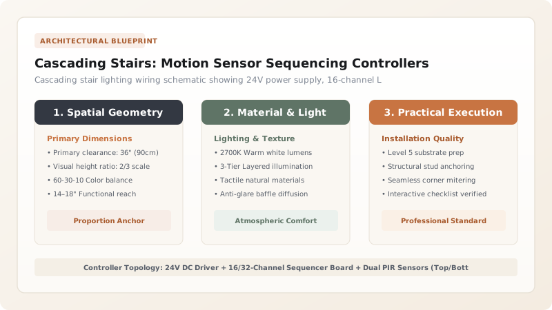
1. Controller Architecture: Multi-Channel Sequencers & PIR Sensor Placement
Standard stair lighting turns all steps on simultaneously like a commercial warehouse. Cascading Stair Lighting uses a dedicated Multi-Channel Micro-Controller Board (such as Skydance or Sunricher 16–32 Channel Controllers).
Concealed PIR Motion Sensors (Passive Infrared) are mounted in the bottom riser (Step 1) and top riser (Step 16) at a height of 18 inches above the landing. Approaching from the bottom illuminates the staircase upward in a gentle wave. Explore router detailing in concealed underside tread routing.

2. Homerun Low-Voltage Wiring Topology & PWM Calibration
Because each step must be individually addressable, you cannot daisy-chain lights in series. Installers pull Dedicated 20/2 AWG CL2 Cable from every single tread back to the central controller.
Configure the Step Speed (typically 300ms–400ms per step) and Dwell Time (30–45 seconds). Review overarching stair principles in illuminated stairs hub.
Staircase Automation Controller Systems Comparison
Use this reference table to calculate exact physical dimensions, ratios, and specifications before purchasing:
| Control Technology | Wiring Method | Sequencing Capability | Smart Home Integration |
|---|---|---|---|
| Dedicated Multi-Channel Sequencer (Optimal) | Individual 2-wire homerun per step | 100% Smooth directional cascading | Dry-contact trigger / DMX / 0-10V |
| Addressable SPI / WS2812B Pixel Tape | Single 3-wire digital data bus | Chasing wave & color effects | High programming required / Fragile data |
| All-On Single Zone Dimmer (Legacy) | Single daisy-chained 2-wire line | 0% (All steps flash on together) | Standard smart switch |
| Battery Puck Sensors (Avoid) | Wireless battery stick-on | Uncoordinated flashing | FAILS: Battery replacements every month |
PIR Sensor False Triggering Constraints
Every successful decoration project must account for physical and environmental constraints:
Pets Walking Past Staircase Hallway Triggering Unwanted Nighttime Cascading
Wide 120° PIR sensors trigger every time a dog walks down the hallway; install 15° narrow-angle optical sensor baffles, aiming sensors strictly across the first tread perpendicular to stair travel, and set sensor sensitivity to ignore low floor heat signatures.
How to Wire, Program, and Commission a Cascading Stair Sequencer
Execute this professional sequence to achieve flawless results without backtracking:
Pull 20/2 AWG Homerun Wires from All Treads
Label and pull individual 20/2 low-voltage cables from each step tread to the central controller location.
Mount Top and Bottom PIR Motion Sensors
Drill 5/8" hole in bottom and top step risers; seat micro-PIR sensor lenses flush with wood face.
Mount 24V Power Supply and Sequencer Board
Install ventilated low-voltage enclosure in under-stair closet; mount 24V Class 2 driver and sequencer.
Terminate Wires to Numbered Controller Terminals
Connect Step 1 to Terminal 1, Step 2 to Terminal 2, continuing in exact chronological step order.
Set Number of Active Steps on Controller Dip Switches
Configure board for exact number of stairs (e.g., set dip switches to 14 active steps).
Calibrate Step Speed, Hold Dwell Time, and Lux Sensor
Tune cascade speed to 350ms/step, set light hold duration to 35 seconds, and calibrate daylight cutoff.
Common Mistakes & Countermeasures
Avoid these costly errors that compromise aesthetics, ergonomics, and budget:
Daisy-Chaining Wires Between Steps on a Cascading System
Project Execution Checklist
Track your physical progress. Checkboxes persist automatically on this device:
Frequently Asked Questions
What happens if a second person starts walking down the stairs while someone is walking up?
Quality sequencer controllers feature multi-directional logic. When the top sensor triggers while an upward sequence is active, the controller lights remaining upper steps immediately, ensuring full illumination for both pedestrians.


